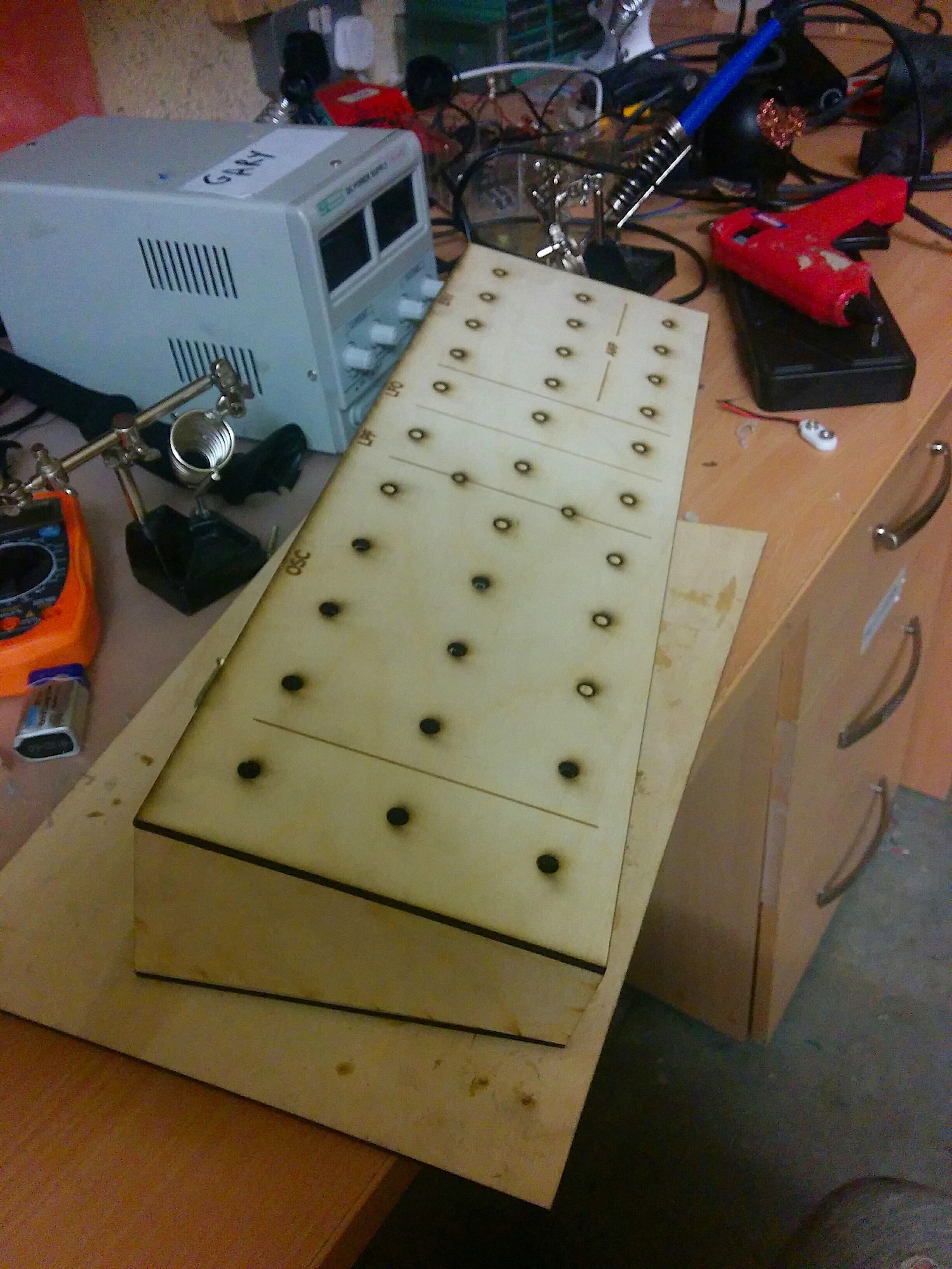
This is the first full synth I have ever tried to make. After a few projects on veroboard I came to despise the stuff and decided to design PCBs instead. I am definitely a designer at heart with a busy schedule and cutting every single wire by hand just doesn’t appeal to me at the moment. I like to think that when I’m older and have the time I will hand build synths slowly and precisely for no other reason that I can take the time to really enjoy it. Until then PCB manufacturing is less time consuming and so much less prone to bad connections and wiring errors. I use JLCPCB to manufacture them and would recommend them to anyone doing hobby electronics. This is no advertisement but I’m just amazed that anyone can design a circuit online and have it manufactured so quickly and cheaply!
Anyway the synth works is serving me well apart from a couple of mistakes I made. The parts are mostly based on MFOS designs, I read his book last year which greatly helped me getting started, and also the Minimoog Service Manual which can be found online. The Minimoog Model D is a legendary synth and even if you don’t know about it you have definitely heard it on many songs throughout the years.
Specification:
±12V Supply
Monophonic
3 Oscillators (Saw, Square-Pulse, Triangle)
4-Pole Low Pass Ladder Filter
Voltage Controlled Amplifier
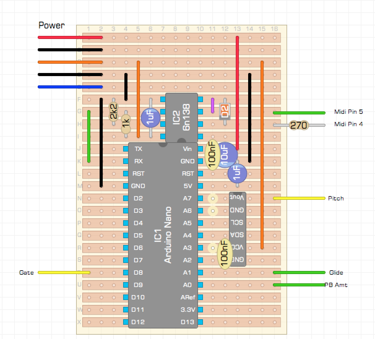
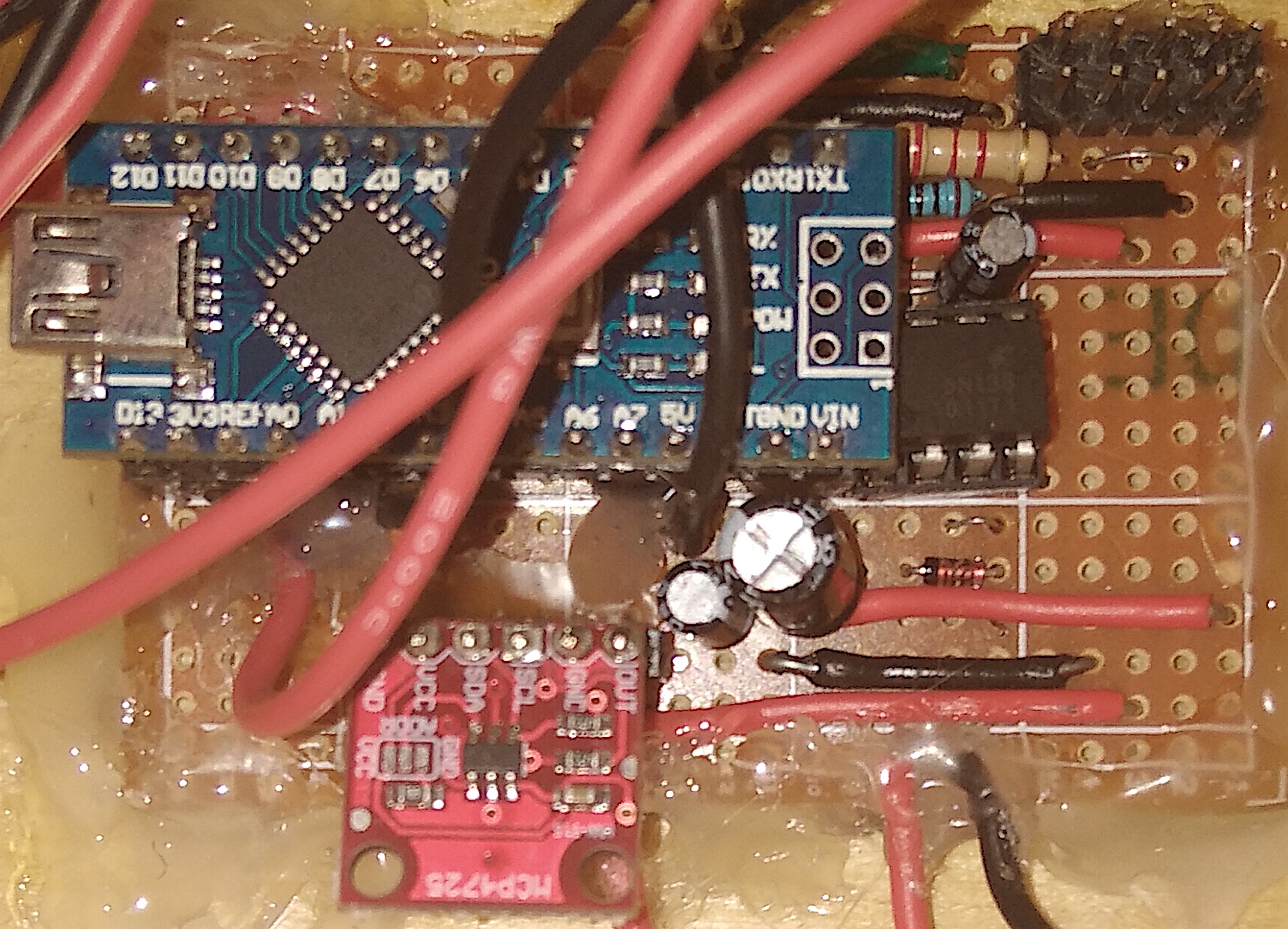
Arduino Nano MIDI Controller
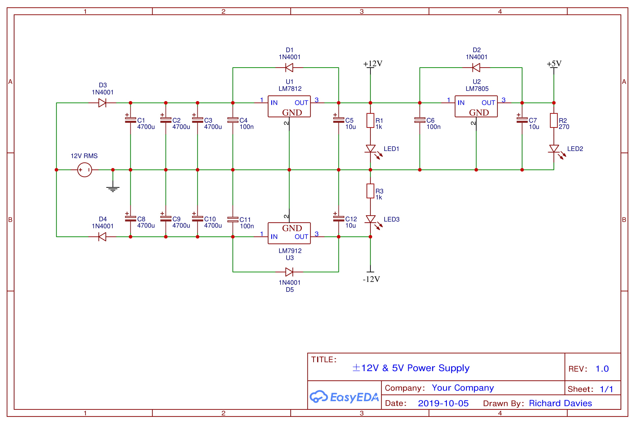
Power Supply
This design is basically my version of the infamous FC power by frequency central. I’m sure it is the same basic circuit but I had to copy it from a picture of the board as there was no schematic online for it.
The basic principle is to use a 12V AC wall socket power supply to generate both a positive and negative supply. The peaks are smoothed by the input capacitors before feeding into LM7X12 series regulators which provide the final ±12V output. The +12V rail also feeds into a LM7805 to create a +5V supply which is used occasionally for certain logic chips and such.
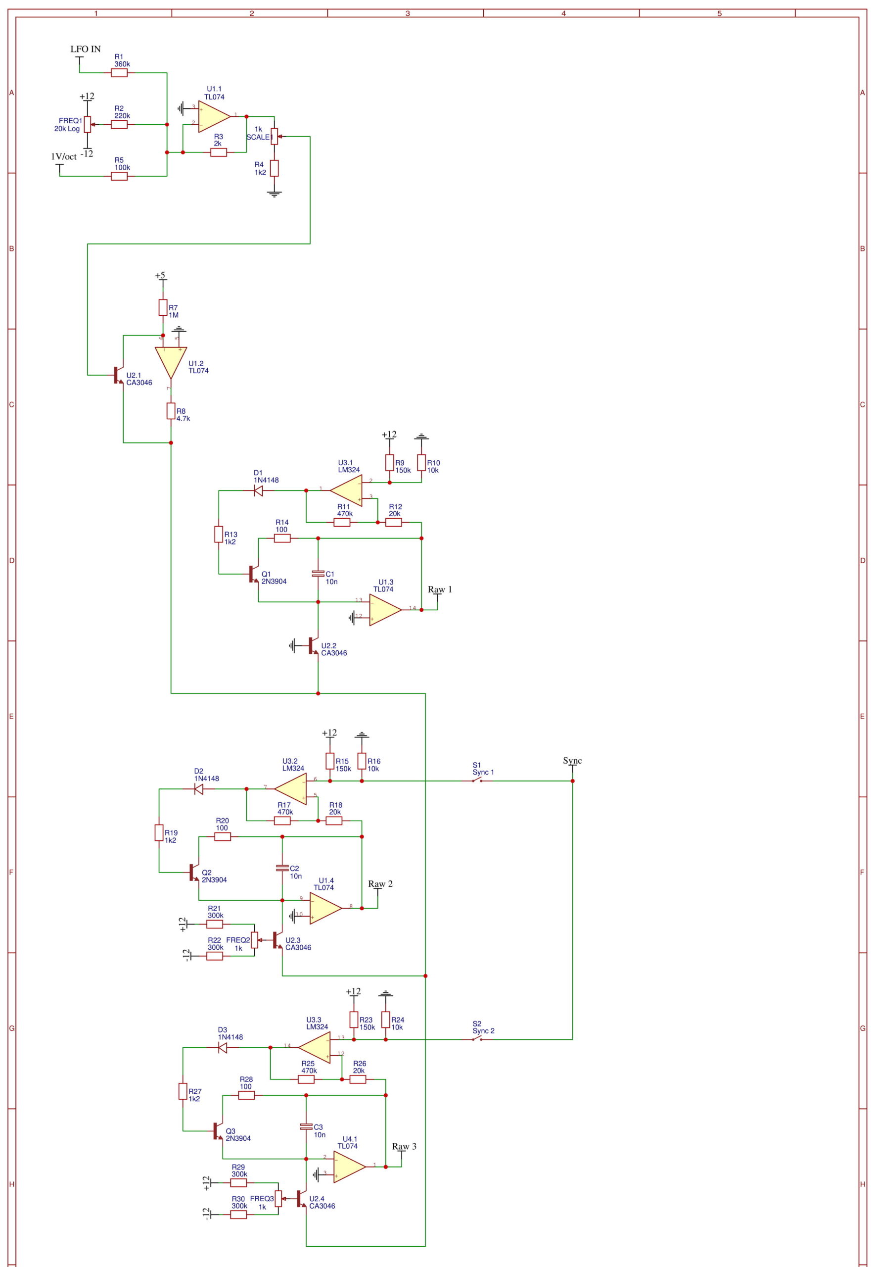
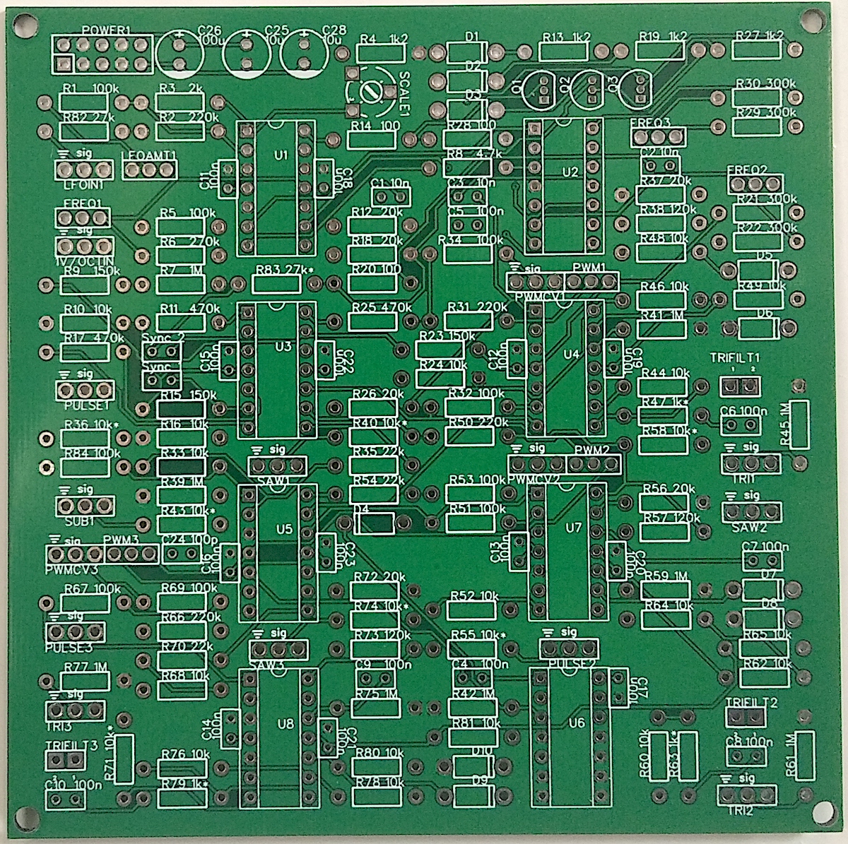
Triple VCO
I have separated the oscillator schematic into two sections as I think it makes it easier to understand. The first section generates 3 raw saw waves, one for each oscillator, which are then shaped to create all the other waveforms. I looked at many designs while learning how oscillators worked by the main two I took inspiration from are from the Minimoog service manual (pg.4) and a design from MFOS.
Saw Core
The principle behind nearly all voltage controlled oscillator designs I have seen is to use a voltage controlled current source to charge a capacitor. When the voltage on the capacitor hits a certain threshold value a gate is opened and the capacitor it is rapidly discharged. The process repeats creating a saw wave voltage on the capacitor.
The voltage controlled current source is a bit more involved to explain so I will provide this link to anyone interested. It does a far better job explaining than I have the patience to do at the moment (sorry :o). The short version is that the current through a BJT transistor is exponentially related to the voltage across two of its terminals. As the voltage difference increases so does the current, and the exponential relationship allows us to control the shape so that for every 1 volt we put into the circuit, the current through the transistor doubles. This gives us the classic 1V/Oct used in commercial synths.
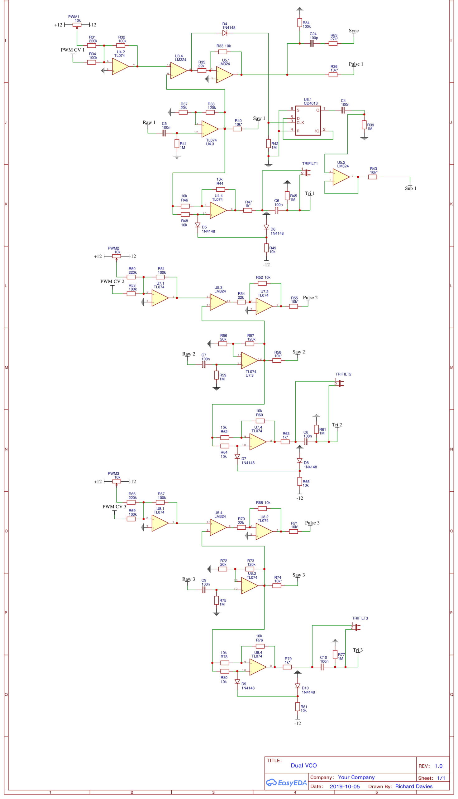
Waveshaping & Sub Osc
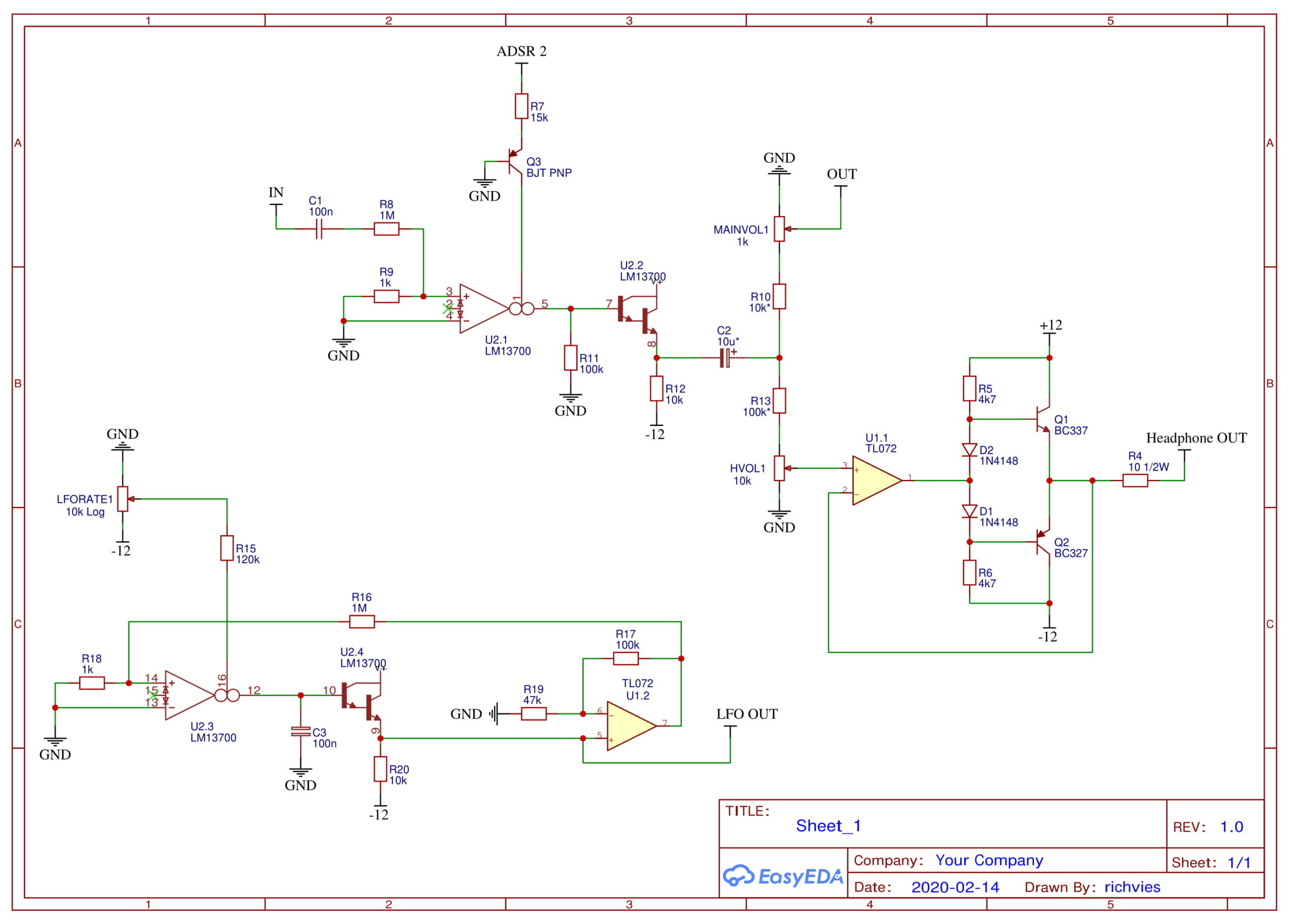
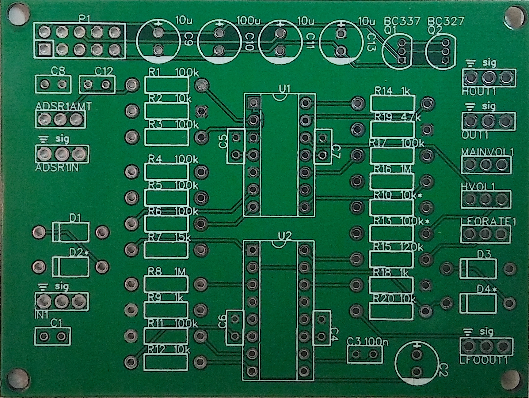
VCA & LFO
The core of these is an LM13700 transconductance amplifier, which basically means you put a voltage in and get a responding current out. By feeding this current through a resistor it becomes a voltage again. The reason for this seemingly roundabout method is that the gain of a transconductance amp is set by a control current. This allows us to use a voltage controlled current source to control the gain of the amplifier i.e. voltage controlled amplifier. VCA designs like this crop up everywhere.
I added a Push-Pull amplifier for the headphone output which is definitely not great. I just picked values that seemed ok and went with it. Now that I look again I didn’t even put a series capacitor on the output (for shame!). Probably not good to rely on it 🙂
The LFO is a basic oscillator produces a triangle wave output. I’ll explain more later.
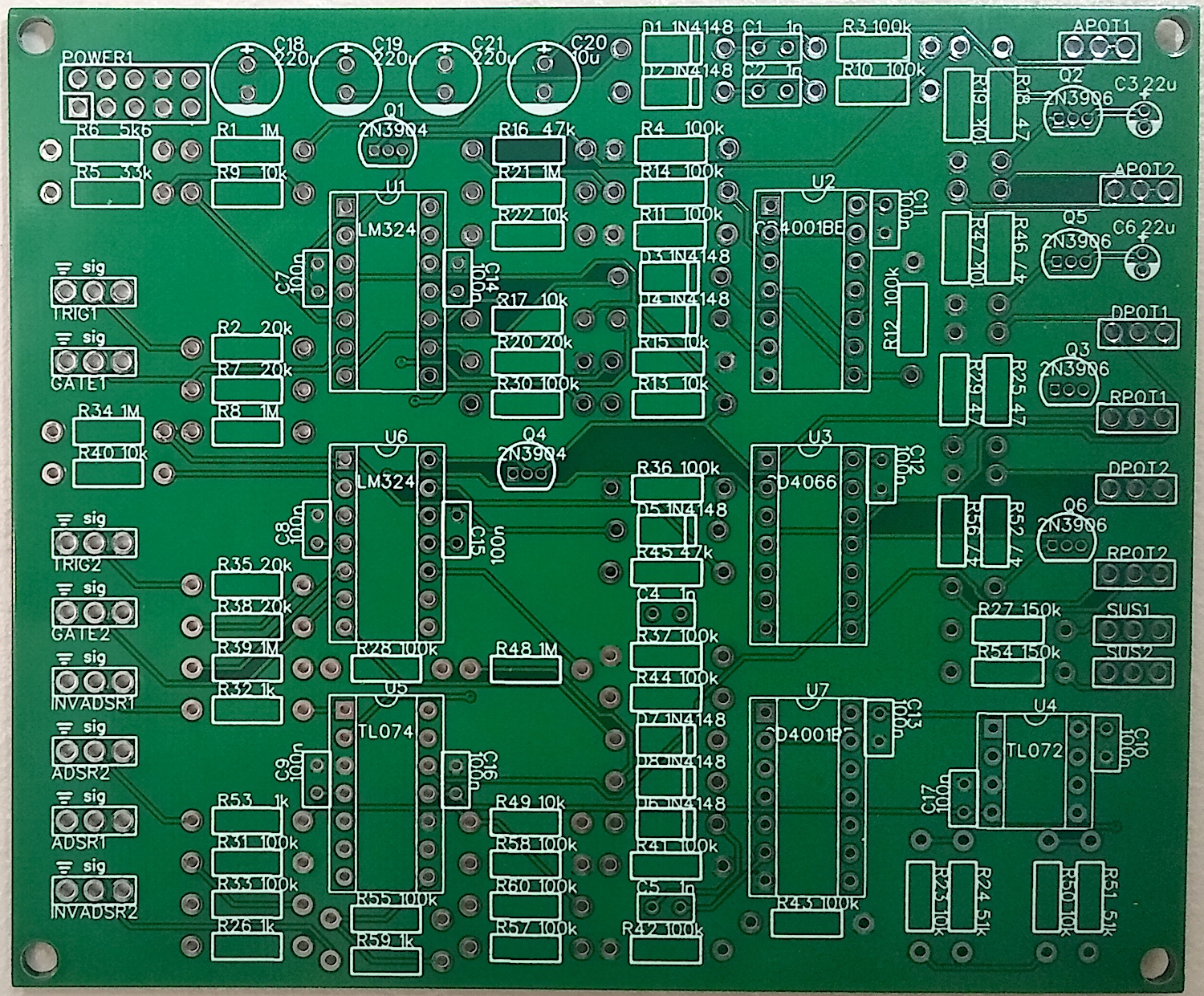
Dual Envelope
Lorem ipsum dolor sit amet, consectetur adipiscing elit. Ut elit tellus, luctus nec ullamcorper mattis, pulvinar dapibus leo.
Arduino
Lorem ipsum dolor sit amet, consectetur adipiscing elit. Ut elit tellus, luctus nec ullamcorper mattis, pulvinar dapibus leo.